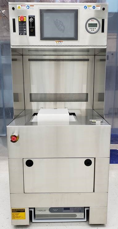
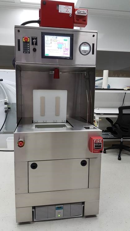
IPA Dryers – Aerosol (Liquid Diffusion Technology)
Have you ever considered the use of IPA dryers (Aerosol) for your wet process? Please contact Wafer Process Systems for more information.
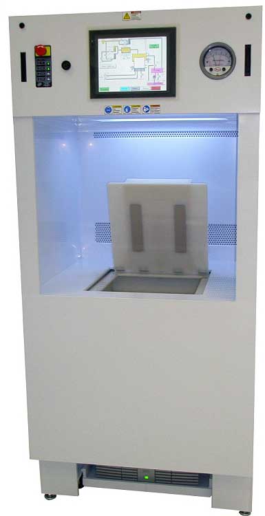
The operator interface is via a colored touch screen panel which provides full graphical display of all process parameters. The touch screen controls incorporate an alarm status panel which prompts the operator in the event of any alarm conditions. A maintenance screen panel which allows service personnel the ability to control all functions manually and to calibrate temperature indicators and auto tune all PID software functions. The integral database provides the ability to create multiple recipes and download from process recipe select screen. All systems incorporate UL, CSA or CE listed, electrical components. All system electrical components and DI Water components are guaranteed for three years and provide a 98% uptime.
Applications Include:
- Front End On Line / Back End Off Line
- Thin Fragile Wafers
- Flat Panel Displays
- Disc Drive Media Drying after Cleaning
- Hydrophobic Surfaces
- Close-Spaced, Half-Pitch Wafer Drying
- High Aspect Ratio / Deep Trench Drying
- MEMS and other Sensitive Devices / Substrates
- Quartz, Sapphire, and other High Purity Materials
- GaAs and other III-V, II-VI Compound Semiconductors
- 32 nm Particle Neutral Drying
- Motionless Substrate Process
Benefits Include:
- High Reliability and Low COO
- Consistent and Repeatable Results
- Propriety Venturi Aerosol Maker™
- Patent-Pending Passive Aerosol Drying
- Super-Efficient IPA Usage @ 40-100 ml Per Cycle
- IPA Liquid Diffusion Technology™ Watermark Free
- Environmentally Friendly, US-EPA Effluent Compliant
- Always Clean™ Proprietary IPA Filtration & Dispense
Optional Features for Our IPA Dryers (Aerosol)
- Megasonic Cleaning Enhanced IPA Aerosol Dryer for the removal of nano-scale particles from photomasks is of critical importance to the implementation of EUV lithography for 32nm node. Megasonic Cleaning has traditionally been used for photomask cleaning and extensions to sub 50nm particulates removal is being considered as a pattern damage free cleaning approach.
- HF Acid Pre Etch to remove native oxides from wafer surface. FM 4910 PVC-C materials of construction are used for pre-treatment processes.
- HCL Acid Pre Etch to remove metal ions contamination from wafer surface. FM 4910 PVC-C materials of construction are used for pre-treatment processes.
- 304 stainless steel constructed weldment with #4 finished and integral secondary containment plenum.
- 316 stainless steel constructed weldment with mirror polished finished and integral secondary containment plenum.
- CO2 or DI Water / N2 Fine Water Mist flame suppression systems with dual mode UV/IR flame detectors using all sub-assemblies on components and reviewed by a third party for coverage calculations.
304 stainless steel constructed weldment with #4 finished.
Particle Performance
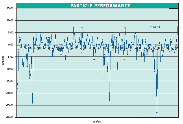
With 200 mm hydrophilic silicon wafers the Liquid Diffusion Technology (LDT) dries with particle neutral performance or better at 32 nm that is watermark free, regardless of wafer load size. These particle performance results were obtained and tested for particle performance at a customer’s site while running actual application processes. A manual stand-alone IPA dryers were used for these tests. Integrated dryers show even lower particle adders as a result of Megasonic Cleaning and robotic handling. Particle neutral is based upon the average of all wafers in the cassette.
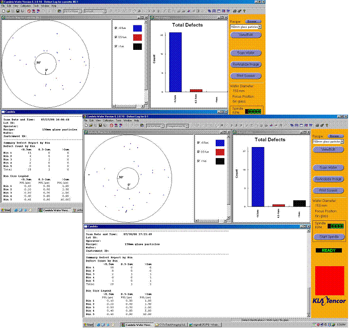
Candela Test Results
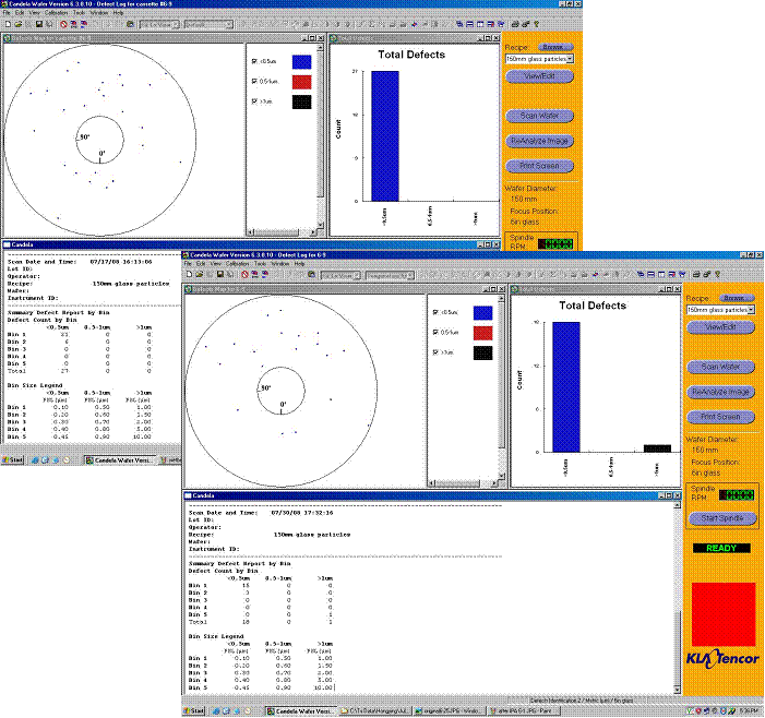
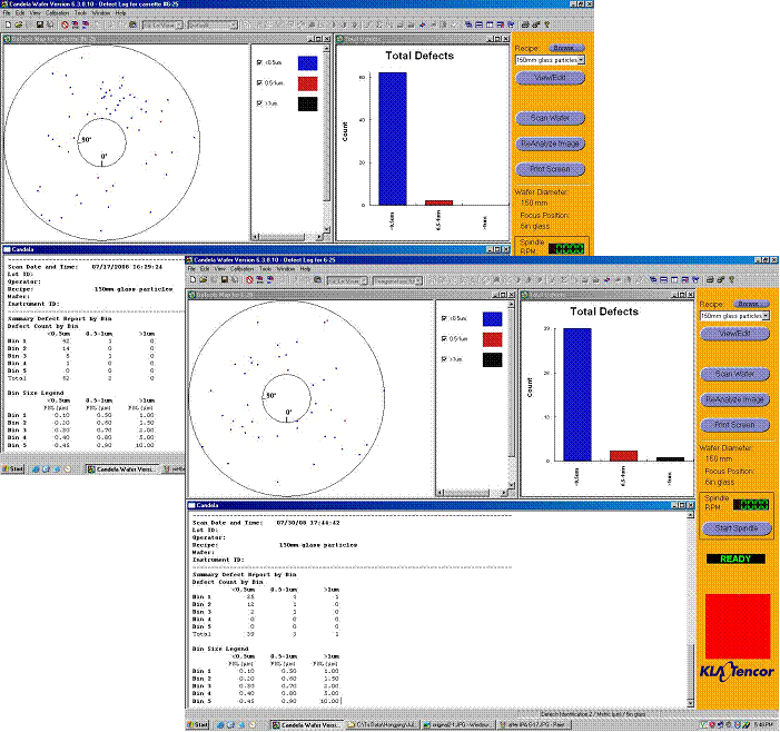
Before and after Candela particle test of quartz wafers process through Megasonic IPA Aerosol Dryer only without any Pre-Clean Process.
N2 Medium: Flow in LPM of N2 manifold during tank fill and IPA build. Typically 5-35 LPM. (1CFM = 28.31 Liters or .17 –1.2 CFM)
Cascade: Time in seconds that the DI Water overflows the process tank at the beginning of the process. (Typically 0-60 seconds.)
N2 to VAM IPA Layer Build Flow:N2 Flow for the VAM during IPA Build sequence. Typically 3-15 LPM (1CFM = 28.31 Liters or .10 –.52 CFM)
IPA Layer Build Timer: Time in seconds that the IPA is dispensed prior to the Slow Drain Sequence. Typically 25-180 seconds. (180 seconds is Recommended).
Drain Speed: Speed in mm/sec that the water drains in the process tank during slow drain. Typically 0.5 to 4mm / sec. (1mm is Recommended).
N2 to VAM Dispense Flow:N2 Flow for the VAM during Slow Drain sequence. Typically 3-15 LPM (1CFM = 28.31 Liters or .10 –.52 CFM)
N2 Manifold Drain Routine: Flow in LPM of N2 typically 5-35LPM. (1CFM = 28.31 Liters or .17 –1.2 CFM)
N2 Warm Flow: Flow in LPM the N2 flows through the manifold during the N2 warm sequence. Typically 80-200LPM (1CFM = 28.31 Liters or 2.82 –7.06 CFM)
N2 Warm Timer: Time is seconds N2 is in high flow and heater actively maintaining set-point. (Process Defined)
N2 Warm Set-Point: Set-Point in C° for the heater during N2 Warm sequence. Typically 180-225 Celsius.
N2 Cool Flow: Flow in LPM the N2 flows through the manifold during the N2 Cool sequence. Typically 80- 200LPM (1CFM = 28.31 Liters or 2.82 –7.06 CFM)
N2 Cool Timer: Time in seconds N2 is in high flow and heater is not active. (Process Defined)
IPA Usage:15-100 ml Per Cycle. (Process Defined. Varies with size of process chamber and size of substrate). Seagate process specs will require approximately 15-20 mL per cycle. (Of the total amount used per cycle 80% or 16 mL will diffuse and go down the drain to facilities AWN. The remaining 20 % or 4 mL will flash and vaporize an enter the exhaust. This occurs during the heated drying cycle after the DI water has drained.
IPA Reservoir Size:1.16 Gallons when full. (3785 ml per gallon = 37 cycles per gallon @ 100ml per cycle)
Background of Megasonic Cleaning Technologies
Megasonics are emerging as an increasingly important, widely accepted cleaning method for contamination-sensitive products. A growing number of manufacturers in the integrated circuit, hard drive, raw silicon, mask, flat panel display, and other industries affected by contamination are turning to megasonic cleaning to help meet stringent cleanliness requirements.
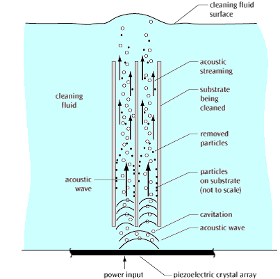
Megasonic cleaning uses the piezoelectric effect to enable removal of submicron particles from substrates. A ceramic piezoelectric crystal is excited by high-frequency AC voltage, causing it to vibrate. This vibration generates an acoustic wave that is transmitted through a cleaning fluid, producing controlled cavitation. As the wave passes across the surface of an object, it causes particles to be removed from the material being cleaned. The technology was originally developed by the U.S. Navy as an element in anti-submarine warfare.
How does it work?
Megasonics work by generating controlled acoustic cavitation in the cleaning fluid. Acoustic cavitation is produced by the pressure variations in sound waves moving through a liquid.
Cavitation, the formation and activity of bubbles (or cavities), is believed to be an important mechanism in the actual particle removal process, because cavitation has sufficient energy to overcome particle adhesion forces and cause particles to be removed. Controlled megasonics cavitation becomes acoustic streaming, which pushes the particles away so they don’t reattach to the material being cleaned.
The pressure amplitude, or megasonic power, required to achieve cavitation has been proven to depend on the pulse width, dissolved gas content in the cleaning fluid, and the power input. Megasonics cleaning is controlled by varying the power input. Pulsing the input power provides better control over cavitation than applying continuous input power.
Exposure time and megasonic power are the most significant variables affecting megasonics cleaning. As megasonic power or exposure time increases, particle redeposition decreases. Pulsed input power (pulsed-wave megasonics) achieves greater acoustic power levels in a cleaning bath than continuous input power (continuous-wave megasonics) at the same average input. Typical exposure times are 10 to 30 minutes.
Megasonics cleaning compared to ultrasonic cleaning:
The difference between ultrasonic cleaning and megasonics cleaning lies in the frequency that is used to generate the acoustic waves. Ultrasonic cleaning uses lower frequencies; it produces random cavitation. Megasonics cleaning uses higher frequencies at 1000 kHz; it produces controlled cavitation.
An important distinction between the two methods is that the higher megasonic frequencies do not cause the violent cavitation effects found with ultrasonic frequencies. This significantly reduces or eliminates cavitation erosion and the likelihood of surface damage to the product being cleaned. Parts that would be damaged by ultrasonic frequencies or cavitation effects can often be cleaned without damage in a megasonic bath using the same solution.
The megasonics cleaning technique is effective for removing 0.15-micron particles from silicon wafers and other products, without damage. The method is currently being used by manufacturers of integrated circuits, flat panel displays, and hard disks, as well as by mask makers and raw silicon suppliers.
Megasonics cleaning may be used with a variety of chemistries. Although it is used primarily for particle removal, it may also be used to increase the efficiency of chemical cleaning with surfactants or detergents. Removal of other contaminants depends on the solutions in the vessel.
What is the Boundary Layer as it relates to Megasonic cleaning?
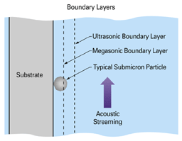
During Megasonic cleaning, the cleaning solution rushes past the substrate being cleaned, forcing chemistry onto contaminant particles, removing them from the surface, and carrying them away. On a microscopic scale, the fluid friction at the surface causes a very thin layer of solution to move more slowly than the bulk solution. This layer of slow-moving fluid at the substrate surface is called the Boundary Layer. The Boundary Layer effectively shields the substrate surface from fresh chemistry and shields contaminants from the removal forces of the bulk fluid.
Boundary layer thickness depends on the following factors
- Frequency of the acoustic wave
- Energy (acoustic intensity) effectively transmitted to the solution
- Fluid properties (kinematics viscosity, density)
Why is the Boundary Layer important?
Minimizing the Boundary Layer is essential to optimal particulate removal and transport, high chemistry refresh rates, and chemical access to surface features. The reduced fluid flow in the Boundary Layer negatively impacts the processes in the following manner:
- Particles are shielded from the flow of the cleaning solution, and remain on the substrate.
- Fresh chemistry does not effectively reach the interface of small surface features leaving strip residues or under-etched devices.
- Cleaning times may be unacceptably long.
How is the Boundary Layer reduced?
The Boundary layer can be reduced in the following ways:
- Increase the acoustic frequency. Boundary layer thickness decreases with increased frequency (0.5μ at megasonic frequencies as compared to 2.5μ at ultrasonic frequencies).
This effect is especially important in removing small particles and accessing small surface features.
- Transmit more energy (acoustic intensity) to the solution. Higher energy results in a thinner Boundary Layer. Pulsed wave megasonics transmits significantly more energy than continuous wave megasonics.
- Increase acoustic streaming. Acoustic streaming is the fluid motion induced by the velocity gradient near a small bubble under megasonic vibration. Acoustic streaming is a function of frequency and delivered intensity.
Acoustic streaming has several important effects.
- The primary effect is the strong localized flow of cleaning solution, whose shear force is the primary particle removal agent. Boundary Layer thickness decreases with increase in this fluid velocity.
- The small, controlled cavitation bubbles generated by pulsed wave megasonics remove contaminants with in the thinner Boundary Layer. Acoustic streaming enhances the transport of particles once they are detached (both within and outside the Boundary Layer).
Benefits of Decreasing the Boundary Layer.
- Decreasing the thickness of the Boundary Layer has the following benefits.
- Increased removal of sub 0.5(μ particles (particles previously protected by the Boundary Layer ).
- Increased particle removal overall.
- Increased transport of removed particles through increased acoustic streaming.
- Higher chemistry refresh rate at the substrate surface resulting in faster cleaning.
- Increased chemical access to small surface features for enhanced etch or strip applications.

